
Hae usein kysyttyjä kysymyksiä
How do I add Hyesteresis Logic in ClearSCADA?
If logic is being used to turn an output on/off based on the value of a process value compared to a setpoint there is the possibility that the process value may "flutter" just above and below the setpoint value. This behaviour would cause the output to continuously cycle on and off which could potentially cause damage to the output and exhibit unwanted behaviour.
Hysteresis logic can be used to provide an "ON" setpoint as well as an "OFF" setpoint. The output would only turn on once the "ON" setpoint threshold is exceeded by the process value and the output would only turn off once the process value drops below the "OFF" setpoint threshold.
Below is an example of how such logic could work in ClearSCADA.
In this example internal digital and analog points have been created to simulate the controlling of a pump (pump) based on the value of a process value (DNP3 AIN). The database structure and the ladder logic (New Ladder Diagram) are as follows:
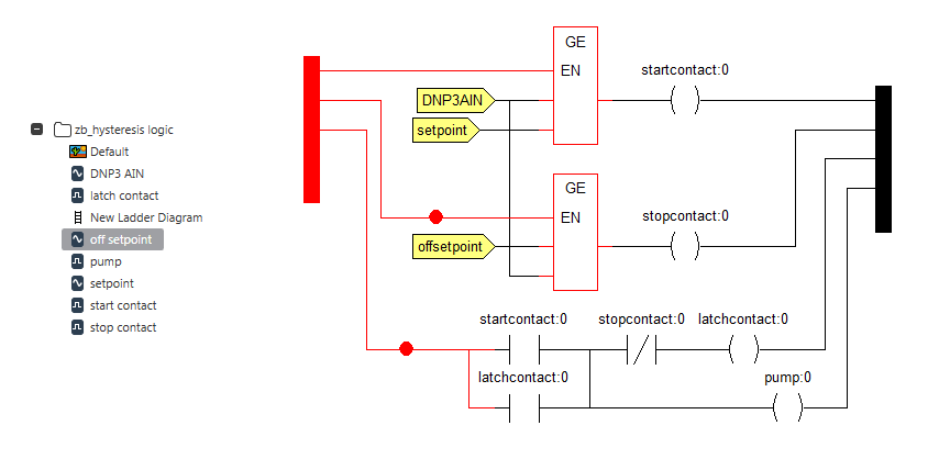
The ladder logic uses 'compare function blocks' (GE - Greater Than or Equal To) to compare the value of the process value (DNP3 AIN) to the values of the setpoints (setpoint, off setpoint).
When running, the results look like this:
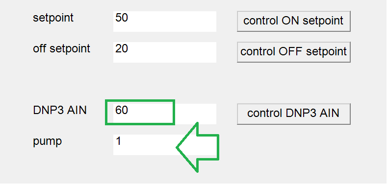
For this example the "ON" setpoint has been set to a value of 50 and the "OFF" setpoint has been set to a value of 20. This means that the process value (DNP3 AIN) must exceed a value of 50 in order to trigger the pump (pump) to turn on.
This first screen shot shows (DNP3 AIN) with a value of 60. In the logic the (start contact) coil turns on while the (stop contact) coil remains off. The latching logic rung at the bottom of the logic turns on the (latch contact) coil which latches itself on and turns on the (pump) coil.
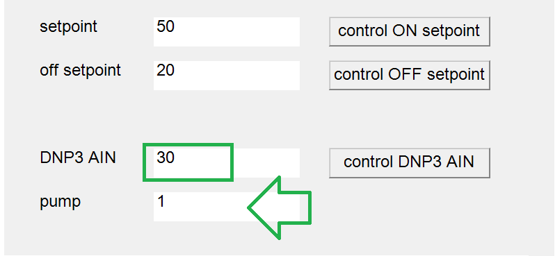
The second screen shot shows that (DNP3 AIN) has dropped to a value of 30 which happens to be in between the "ON" and "OFF" setpoints. In the logic the (start contact) turns off and the (stop contact) remains off. The (latch contact) coil remains on due to the latching logic which in turn keeps the (pump) coil in the on state.
The third screen shot shows that (DNP3 AIN) has dropped to a value of 15 which is below the "OFF" setpoint. In the logic the (start contact) remains off and the (stop contact) turns on. This breaks the latch which turns off the (latch contact) coil which, in turn, turns off the (pump) coil.
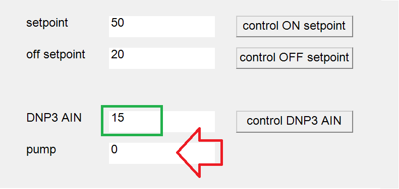
The (pump) coil will remain off until the (DNP3 AIN) point exceeds the (setpoint) value (in this case, 50) at which point the pump will again turn on.
Hysteresis logic can be used to provide an "ON" setpoint as well as an "OFF" setpoint. The output would only turn on once the "ON" setpoint threshold is exceeded by the process value and the output would only turn off once the process value drops below the "OFF" setpoint threshold.
Below is an example of how such logic could work in ClearSCADA.
In this example internal digital and analog points have been created to simulate the controlling of a pump (pump) based on the value of a process value (DNP3 AIN). The database structure and the ladder logic (New Ladder Diagram) are as follows:
The ladder logic uses 'compare function blocks' (GE - Greater Than or Equal To) to compare the value of the process value (DNP3 AIN) to the values of the setpoints (setpoint, off setpoint).
When running, the results look like this:
For this example the "ON" setpoint has been set to a value of 50 and the "OFF" setpoint has been set to a value of 20. This means that the process value (DNP3 AIN) must exceed a value of 50 in order to trigger the pump (pump) to turn on.
This first screen shot shows (DNP3 AIN) with a value of 60. In the logic the (start contact) coil turns on while the (stop contact) coil remains off. The latching logic rung at the bottom of the logic turns on the (latch contact) coil which latches itself on and turns on the (pump) coil.
The second screen shot shows that (DNP3 AIN) has dropped to a value of 30 which happens to be in between the "ON" and "OFF" setpoints. In the logic the (start contact) turns off and the (stop contact) remains off. The (latch contact) coil remains on due to the latching logic which in turn keeps the (pump) coil in the on state.
The third screen shot shows that (DNP3 AIN) has dropped to a value of 15 which is below the "OFF" setpoint. In the logic the (start contact) remains off and the (stop contact) turns on. This breaks the latch which turns off the (latch contact) coil which, in turn, turns off the (pump) coil.
The (pump) coil will remain off until the (DNP3 AIN) point exceeds the (setpoint) value (in this case, 50) at which point the pump will again turn on.